- info@nuteckcouplings.com
- +91 20 27120103 / 27120104

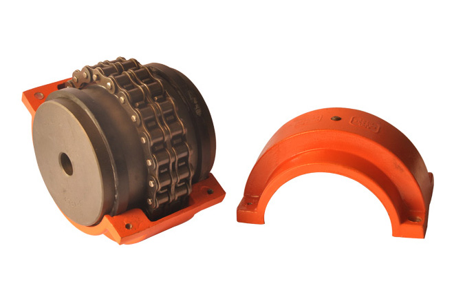
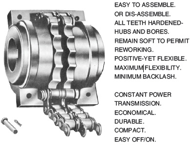
Roller Chain Flexible Couplings
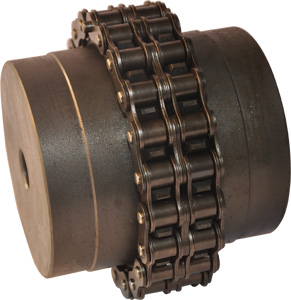
Nu-Teck Roller Chain Flexible Couplings are compact, all steel, long lasting flexible couplings, capable of transmitting relatively high torques with minimum space consumption. Consequently, they provide a most economical means of positive transmission of power from one shaft to another. The simple design and construction of these couplings make them extremely easy to install and disconnect, providing additional economy of operation.
The sprockets are identical in construction, thus providing a balanced unit in operation and reducing effects of vibration. In addition, the flexibility of roller chain plus clearance between the chain rollers and sprocket teeth allow for slight misalignment and shaft end float.
Stock couplings sizes will usually meet most power transmission requirements. However when necessary special couplings can be furnished on a made to order basis to suit a particular application. In such cases, complete information should be given when requesting a recommendation or quotation. This includes horsepower and RPM requirements, hub dimensions, bore and keyway sizes, and general operating conditions.
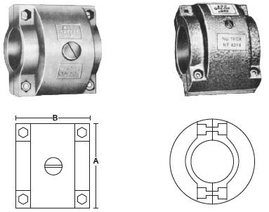
| Coupling No. | ASA No. | A | B | Wt. Kg. |
| NT 6112 | 3812 | 69 | 59 | 0.2 |
| NT 8312 | 4012 | 75 | 68 | 0.2 |
| NT 8316 | 4016 | 90 | 70 | 0.4 |
| NT 1016 | 5016 | 114 | 86 | 0.6 |
| NT 1018 | 5016 | 123 | 90 | 0.8 |
| NT 1218 | 6018 | 149 | 93 | 1.2 |
| NT 1222 | 6022 | 173 | 110 | 1.6 |
| NT 1618 | 8018 | 195 | 135 | 2.3 |
| NT 1622 | 8022 | 222 | 134 | 2.4 |
| NT 2020 | 10020 | 258 | 174 | 3.4 |
| NT 2418 | 12018 | 292 | 218 | 5.9 |
| NT 2422 | 12022 | 340 | 212 | 7.3 |
| NT 3218 | 16018 | 385 | 250 | 14 |
Selection of the Size of the Couplings
Decide the service factor for the unit for which the chain coupling is to be fitted by considering the following :
- hours of service
- type of power unit etc. from the following table
| Service Classification |
Driven equipment | Source of power | |||
| kinds | characteristics | Electric motor or steam turbine |
Steam or gasoline engine 4 or more cyl. |
Diesel or Gas Engine |
|
| A |
|
|
1 | 1.5 | 2.0 |
| B |
|
|
1.5 | 2.0 | 2.5 |
| C |
|
|
2.0 | 2.5 | 3.0 |
- For 8 to 16 hrs/day service, use the next step service factor.
- For 16 to 24 hours/day service, use service factor two step higher loading.
- Multiply horsepower of the driver unit by the service factor. This is design horsepower.
- Note the maximum rpm. at which the unit will run and its shaft diameter.
- From the H.P. rating table, select the coupling size which is rated equal to or slightly greater than design H.P. required at the rpm. at which the coupling is to operate.
- Also, make sure that the diameter at the shaft is less than the maximum bore permissible on the coupling. If the coupling is not large enough to accommodate the shaft size, use the next coupling which can be bored to suit the shaft requirement.
H. P. Ratings.
| Coupling No |
Equisasa No. |
Max Bore |
Revolution Per Minute | |||||||||||||||||||||||
| 1 | 5 | 10 | 25 | 50 | 100 | 200 | 300 | 400 | 500 | 600 | 800 | 1000 | 1200 | 1500 | 1800 | 2000 | 2500 | 3000 | 3600 | 4000 | 4800 | 5200 | 6000 | |||
| NT 6112 | 3812 | 16 | 0.013 | 0.066 | 0.146 | 0.346 | 0.693 | 1.053 | 1.613 | 2.106 | 2.520 | 3.013 | 3.440 | 4.253 | 5.173 | 5.880 | 7.133 | 8.333 | 8.973 | 10.82 | 12.58 | 14.66 | 16.00 | 18.86 | 19.73 | 22.26 |
| NT 8312 | 4012 | 22 | 0.026 | 0.146 | 0.146 | 0.773 | 1.533 | 2.306 | 3.506 | 4.613 | 5.533 | 6.613 | 7.560 | 9.346 | 11.38 | 12.90 | 15.46 | 18.26 | 19.73 | 23.56 | 27.60 | 32.13 | 35.06 | 41.06 | ||
| NT 8316 | 4016 | 32 | 0.053 | 0.280 | 0.546 | 1.373 | 2.746 | 4.120 | 6.253 | 8.226 | 9.880 | 11.80 | 13.46 | 16.66 | 20.40 | 23.06 | 28.00 | 32.53 | 35.06 | 42.53 | 49.33 | 57.33 | 62.53 | 73.20 | ||
| NT 1016 | 5016 | 42 | 0.106 | 0.520 | 1.040 | 2.600 | 5.213 | 7.813 | 11.89 | 15.60 | 18.80 | 22.40 | 25.60 | 31.73 | 38.53 | 43.86 | 53.20 | 61.86 | 66.66 | 80.80 | 93.86 | 108.80 | ||||
| NT 1018 | 5018 | 48 | 0.133 | 0.666 | 1.320 | 3.306 | 6.600 | 9.906 | 15.06 | 19.86 | 23.73 | 28.40 | 32.53 | 40.13 | 48.80 | 55.46 | 66.733 | 78.40 | 84.53 | 102.40 | 118.13 | |||||
| NT 1218 | 6018 | 60 | 0.240 | 1.240 | 2.493 | 6.226 | 12.44 | 18.66 | 28.40 | 37.33 | 44.80 | 53.46 | 61.20 | 75.73 | 92.13 | 104.53 | 126.93 | 148.0 | 160.0 | 193.33 | ||||||
| NT 1222 | 6022 | 76 | 0.333 | 1.666 | 3.346 | 8.413 | 16.66 | 25.06 | 38.13 | 50.26 | 60.40 | 72.13 | 82.53 | 102.0 | 124.13 | 140.0 | 170.66 | 198.66 | 214.66 | 260.0 | ||||||
| NT 1618 | 8018 | 80 | 0.546 | 2.760 | 5.520 | 13.73 | 27.60 | 41.33 | 62.93 | 82.80 | 99.33 | 118.66 | 134.66 | 168.0 | 204.0 | 232.0 | 281.33 | 328.0 | 353.33 | |||||||
| NT 1622 | 8022 | 95 | 0.786 | 3.946 | 7.906 | 19.73 | 39.46 | 59.33 | 89.60 | 118.66 | 141.33 | 169.33 | 194.66 | 240.0 | 292.0 | 332.0 | 402.6 | 469.33 | 505.33 | |||||||
| NT 2020 | 10020 | 110 | 1.240 | 6.213 | 12.44 | 31.06 | 62.13 | 93.33 | 141.33 | 166.66 | 224.0 | 266.66 | 305.33 | 377.33 | 460.0 | 522.66 | 634.66 | 738.66 | ||||||||
| NT 2418 | 12018 | 119 | 1.866 | 9.360 | 18.66 | 46.80 | 93.60 | 140.0 | 213.33 | 280.0 | 336.0 | 402.6 | 460.0 | 568.0 | 692.0 | 786.86 | 954.66 | |||||||||
| NT 2422 | 12022 | 150 | 2.413 | 12.09 | 24.13 | 60.40 | 120.93 | 181.33 | 274.66 | 362.66 | 434.66 | 520.0 | 594.66 | 734.66 | 894.66 | 1016.0 | ||||||||||
| NT 3218 | 16018 | 160 | 4.040 | 20.13 | 40.40 | 101.06 | 201.33 | 302.66 | 460.0 | 606.66 | 728.0 | 869.33 | 994.66 | 1229.3 | 1496.0 | |||||||||||
| NT 3222 | 16022 | 199 | 5.906 | 29.46 | 59.06 | 146.66 | 294.66 | 444.00 | 674.66 | 886.68 | 1065.3 | 1272.0 | 1453.3 | 1800.0 | 2186.6 | |||||||||||
| NT 4018 | 20018 | 205 | 8.080 | 40.40 | 80.80 | 201.33 | 404.00 | 605.33 | 921.33 | 1212.0 | 1453.3 | 1733.3 | 1986.6 | 2453.3 | ||||||||||||
| NT 4022 | 20022 | 260 | 10.17 | 50.93 | 101.73 | 254.66 | 509.33 | 762.66 | 1161.33 | 1520.0 | 1826.6 | 2186.6 | 2506.6 | |||||||||||||
Lubrication
- Couplings operating without covers under fairly clean conditions will give satisfactory service providing they are periodically (weekly) brushed thoroughly with ball bearing grease of medium consistency.
- Couplings operating with covers should be kept filled with a good quality ball bearing grease of soft or medium consistency.
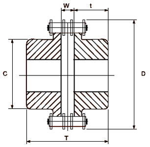
| Coupling No.. |
ASA No. |
Bore | T | t | W | C | D | Wt.Kg. | |
| Min | Max.dfc | ||||||||
| NT 6112 | 3812 | 10.00 | 16 | 65 | 30 | 5.0 | 27 | 45 | 0.30 |
| NT 8312 | 4012 | 10.00 | 22 | 79 | 36 | 7.0 | 35 | 60 | 0.80 |
| NT 8316 | 4016 | 12.00 | 32 | 79 | 36 | 7.0 | 50 | 77 | 1.60 |
| NT 1016 | 5016 | 16 | 42 | 96 | 44 | 8.0 | 61 | 96 | 2.60 |
| NT 1018 | 5018 | 16 | 48 | 98 | 45 | 8.0 | 71 | 106 | 3.50 |
| NT 1218 | 6018 | 20 | 60 | 121 | 56 | 9.0 | 88 | 126 | 6.5 |
| NT 1222 | 6022 | 20 | 76 | 121 | 56 | 9.0 | 110 | 150 | 10.0 |
| NT 1618 | 8018 | 25 | 80 | 150 | 67 | 16 | 115 | 170 | 14.5 |
| NT 1622 | 8022 | 25 | 95 | 150 | 67 | 16 | 140 | 201 | 20.0 |
| NT 2020 | 10020 | 40 | 110 | 200 | 91 | 18 | 157 | 231 | 33.5 |
| NT 2418 | 12018 | 50 | 119 | 260 | 118 | 24 | 169 | 254 | 51.0 |
| NT 2422 | 12022 | 50 | 150 | 260 | 118 | 24 | 208 | 301 | 76.0 |
| NT 3218 | 16018 | 50 | 160 | 360 | 165 | 30 | 220 | 341 | 121.0 |
| NT 3222 | 16022 | 50 | 199 | 360 | 165 | 30 | 280 | 410 | 210.0 |
| NT 4018 | 20018 | 60 | 205 | 517 | 240 | 37 | 295 | 425 | 320.0 |
| NT 4022 | 20022 | 60 | 260 | 517 | 240 | 37 | 373 | 507 | 470.0 |